Scene Interaction
Basic camera and viewport controls for navigating the 3D scene. Each interaction preserves the scene contents while changing only the view, allowing precise inspection and manipulation without altering object transforms.
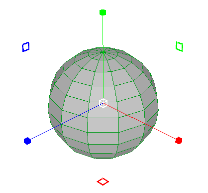
Scene Rotation (X + Left Mouse Button + Drag)
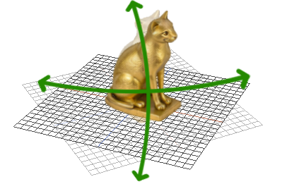
Rotates the entire 3D scene around the scene origin. Hold the X key, press and hold the Left Mouse Button, then drag to orbit the camera smoothly around the central pivot.
This interaction does not move objects — it changes only the camera orientation relative to the scene origin, making it ideal for inspecting proportions, checking silhouettes, and reviewing details from multiple angles.
Tips: combine slow, small drags for precision or larger sweeps for rapid reorientation. Use in conjunction with frame/zoom commands to focus on particular objects while rotating.
Scene Panning (Right Mouse Button + Drag)
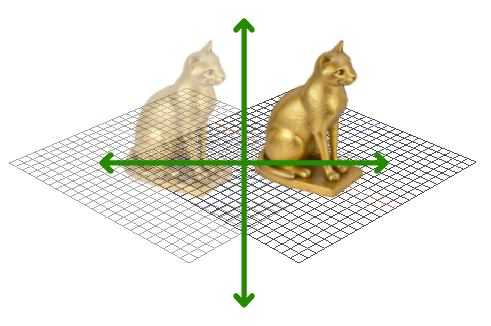
Moves the camera parallel to the view plane. Press and hold the Right Mouse Button and drag to slide your view left/right or up/down without altering the camera's rotation or zoom level.
Panning is useful for repositioning the viewport to focus on off-center details, lining up elements, or adjusting your framing while modeling. It keeps the current viewing direction and distance intact.
Tips: use panning together with zoom to navigate large scenes efficiently — pan to place the area of interest near the center of the view, then zoom in for detail work.
Scene Zoom (Middle Mouse Button + Drag or Mouse Wheel)
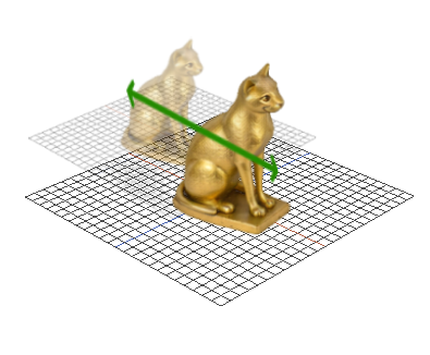
Adjusts the camera distance to the scene, bringing the view closer or farther from the origin. Use the Middle Mouse Button + drag for continuous zoom or the Mouse Wheel for stepped zoom increments.
Zooming is essential for inspecting fine details, laying out scenes at different scales, and quickly switching between overview and focused work. It modifies the camera's translation along the view axis without changing orientation.
Tips: pair zoom with frame-to-selection to center and zoom precisely on selected objects, and use smooth middle-button drags for controlled, gradual zooming when adjusting fine details.
Scene Camera Focus (F Key)
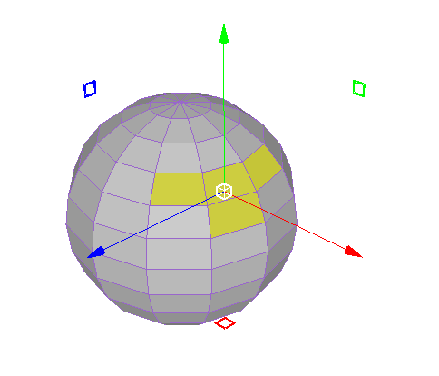
Centers the camera view on the currently selected object, face, edge, or vertex.
Press the F key to immediately move the camera so that the selected
elements become the new pivot point for navigation.
Once focused, all scene interactions—such as rotation, panning, and zooming—revolve
smoothly around this new center point. This makes it much easier to inspect specific
details, work on small components, or adjust complex areas of your model without
losing orientation.
This command is especially valuable when your selection is off-screen or too small
to see clearly. It allows you to instantly snap the camera to a clear, centered view,
restoring a stable and efficient workflow even in dense or large-scale scenes.
Selection Tools
The selection system allows you to interact with 3D geometry at multiple levels—meshes, faces, edges,
vertices, UV faces, UV edges, and UV points. Each method provides precise control over component
selection, enabling efficient modeling and editing workflows.
Click Selection
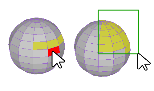
Basic selection is performed by clicking directly on a geometry component. You can click to
select individual elements or click and drag to create a marquee selection area, capturing all
components inside the rectangular region.
Holding the Shift key allows you to add or remove components from the current
selection, enabling flexible multiselection for complex editing tasks.
The combination Ctrl + Shift limits interaction to adding components only,
preventing accidental deselection. This is useful when expanding your selection across the scene.
These click and drag selection methods (Shift, Ctrl, mouse interactions) work consistently across
all editable elements, including geometry, faces, edges, vertices, UV faces, UV edges,
and UV points.
Double-Click Selection
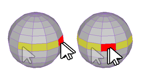
Double-clicking a geometry component selects all connected components of the same type. This is a
fast way to highlight an entire continuous region without manually clicking each part.
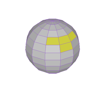
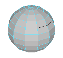
For faces, double-click selection can be used to capture face loops. Simply select
a face, then double-click an adjacent one to select the entire loop following the surface topology.
If you click one face and then double-click a face that lies along the loop path, you will
select a face chain (segment), allowing precise control over partial loop
selections.
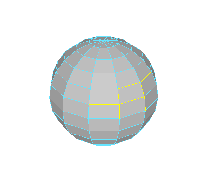
Double-clicking an edge selects an entire edge loop. Similarly, clicking an edge
and double-clicking another along the loop selects an edge chain (segment), giving
you fine control when working with quads.
This double-click selection behavior works across all components—faces, edges, vertices,
UV faces, UV edges, and UV points—making it a universally applicable tool for modeling
and UV editing.
Files
This menu provides tools for starting new projects, importing external 3D assets, and saving or exporting data. It serves as the entry point for managing project files and organizing the workflow.
New Project
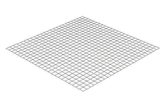
Creates a completely fresh project using the default application settings. This clears any existing objects, materials, or scene data so you can begin building from scratch. It is useful for starting new concepts or resetting an existing workspace.
Ensures a clean working environment with known default configurations.
Import (GLTF, OBJ)
Loads external 3D content into the current scene, supporting both GLTF and OBJ formats. These widely used standards allow importing characters, props, architectural shapes, and other assets created in external 3D applications.
Multiple files can be imported simultaneously, enabling quick assembly of complex scenes.
Save Scene (GLTF)
Saves the entire scene — objects, transforms, materials, and hierarchy — into a GLTF file. This format is efficient, modern, and ideal for exchanging scenes between engines and rendering tools.
Preserves your progress and allows resuming work later without loss of detail.
Export Selected (OBJ)
Exports only the geometries you have selected into an OBJ file. This is particularly useful when you want to isolate pieces of a bigger scene for collaboration, 3D printing, or use in other applications.
The resulting file contains only your targeted assets with no extra clutter.
Create
This menu contains tools for generating new geometric primitives and specialized objects. These shapes serve as foundational building blocks for modeling and sculpting.
Empty
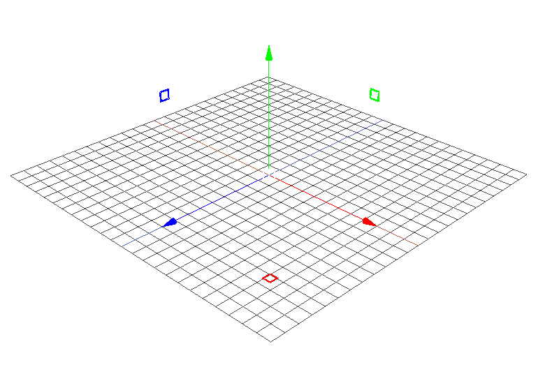
Creates an empty mesh object that contains no vertices or faces. This is ideal when you need to manually construct a model from the ground up, adding geometry incrementally.
Useful for advanced workflows requiring complete custom topology.
Plane
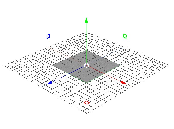
Generates a flat 1×1 cm rectangular surface. A plane is often used as a starting point for large flat forms like floors, walls, panels, or terrain patches.
Its simple geometry makes it easy to subdivide and reshape into more complex structures.
Cube
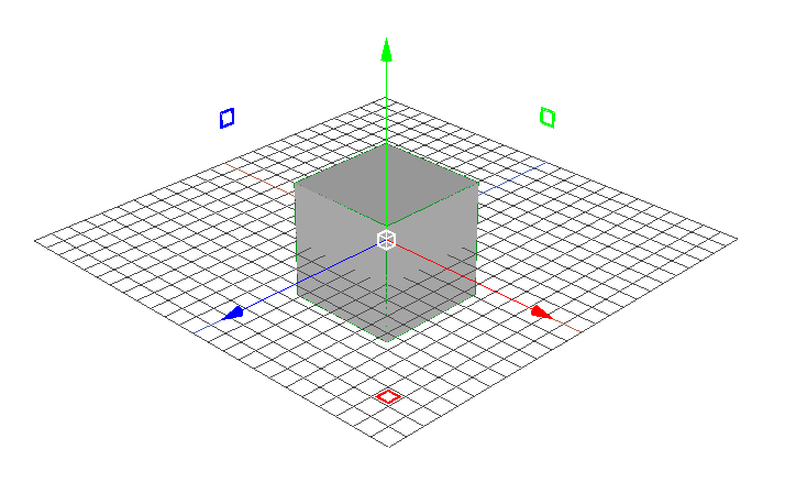
Creates a standard 1×1×1 cm cube primitive. This shape is commonly used for blocking out models, building architectural features, or starting hard-surface designs.
Its evenly distributed faces make it ideal for extrusion and beveling operations.
Cylinder
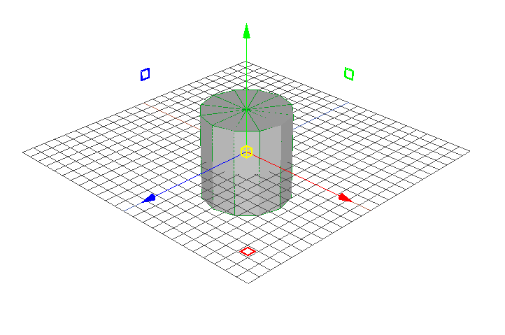
Generates a cylindrical object with evenly spaced segments. Useful for pipes, handles, structural elements, and any shape requiring circular symmetry.
Works well in workflows involving smoothing or subdivision.
Sphere
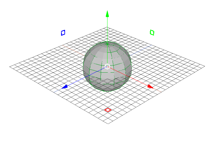
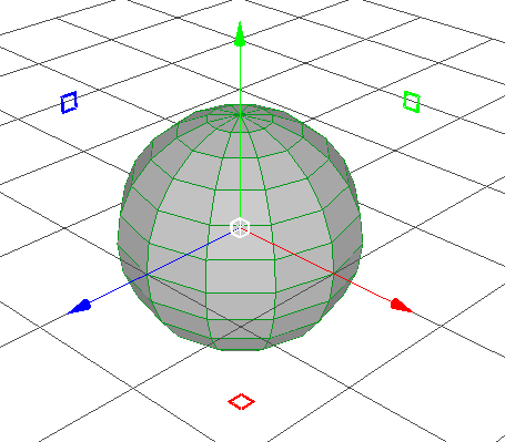
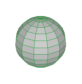
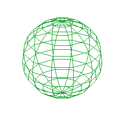
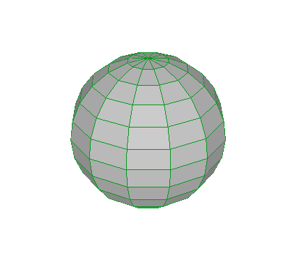
Creates a spherical primitive, ideal for organic shapes such as characters, props, or rounded surfaces. The uniform topology responds well to deformation and sculpting.
A frequent starting point for smooth objects.
Helix
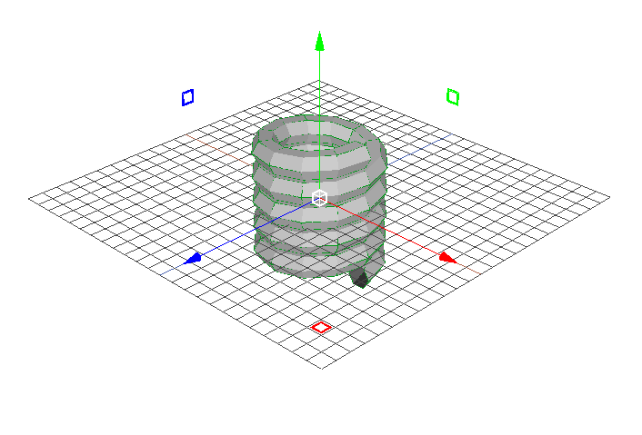
Generates a helical spiral shape. Useful for coils, springs, cables, or decorative elements.
Provides a fast way to obtain complex curved forms that would otherwise be time-consuming to build manually.
Image to 3D
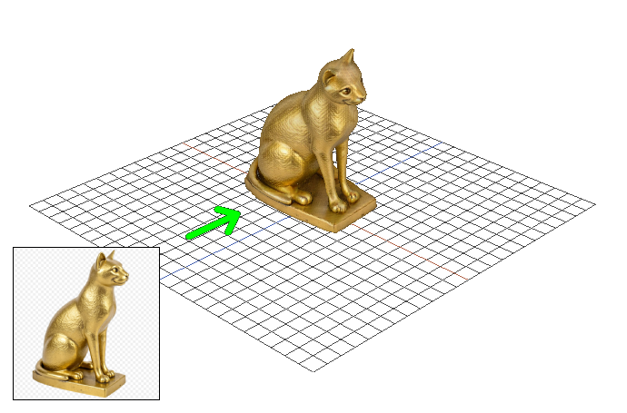
Converts a 2D image into a textured 3D surface by interpreting pixel intensity and contour information. Ideal for reliefs, embossing, imprints, and creating 3D shapes directly from artwork.
This feature automates the transformation of flat imagery into physical geometry.
Mesh Tools
 Export Selected
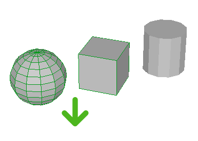
Exports only the selected mesh objects as separated OBJ files. Ideal when sharing specific assets or sending isolated parts of a larger model to collaborators.
Ensures that only the intended objects are selected before exporting.
 Subdivide
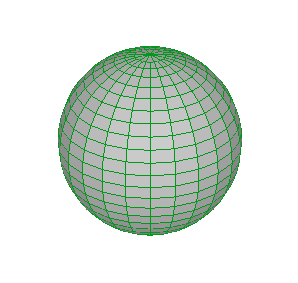
Increases the mesh resolution using the Catmull–Clark algorithm, generating smoother surfaces with additional geometry. This operation is commonly used before sculpting or when preparing models for high-detail rendering.
Maintains the overall shape while greatly enhancing detail potential.
 Optimize
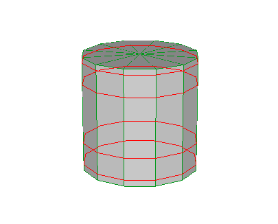
Cleans the current mesh by removing unnecessary vertices, merging overly dense areas, and improving the overall topology. Helps maintain performance and prevents issues caused by irregular geometry.
Ideal for imported meshes or models built from complex operations.
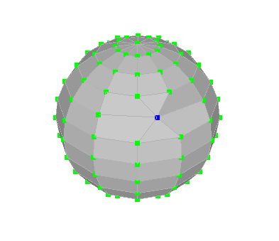
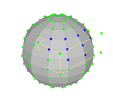
 Deform
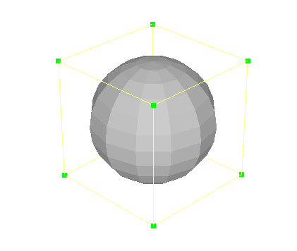
Applies bounding-box deformation, allowing controlled stretching, scaling, or reshaping of the entire geometry. This provides broad shape manipulation while preserving internal mesh connectivity.
Useful for adjusting overall proportions.
 Smart Mirror
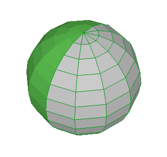
Automatically detects a symmetry plane and mirrors the geometry across it. This speeds up symmetrical modeling tasks and removes the need to manually configure axes.
Ensures accurate bilateral symmetry for characters, vehicles, and other designs.
 Combine
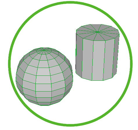
Merges multiple selected objects into a single mesh, unifying them into a continuous model. This is useful when finalizing an object or preparing it for texturing and exporting.
Reduces scene clutter by consolidating parts.
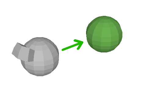
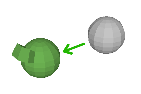
 Clone
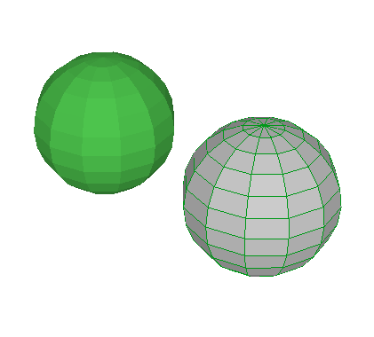
Creates an exact duplicate of the selected geometry while preserving the original's position, scale, and rotation. Ideal for duplicating repeating elements such as tiles, bolts, or decorative features.
 Move Pivot
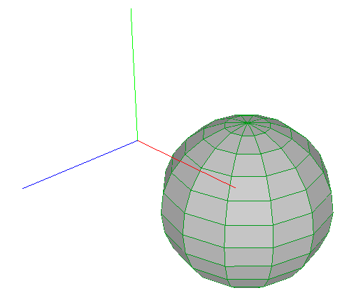
Allows repositioning of the object's pivot, which is crucial for controlling rotation, scaling, and animation behaviors. Adjusting the pivot makes object manipulation more intuitive.
 Center Pivot
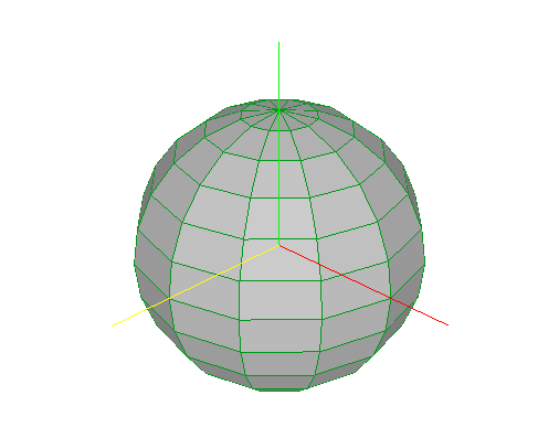
Automatically moves the pivot point to the geometric center of the object. This is useful when an object has been transformed or imported with an offset pivot.
 Hard Normals
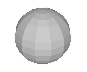
Forces all normals to form sharp angles between faces, giving the model a faceted, mechanical appearance. Ideal for hard-surface components where crisp edges are desired.
 Smooth Normals
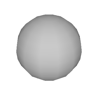
Softens the shading across surfaces by smoothing normals, producing a rounded visual effect. Useful for organic shapes or objects meant to appear polished and smooth.
 Trace Texture
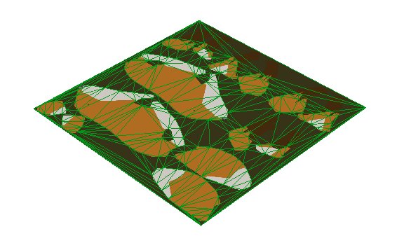
Analyzes the underlying texture and generates additional geometry that matches visible image details. This is useful for converting texture patterns into actual 3D reliefs.
 Displacement Map
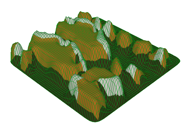
Applies a displacement texture to physically alter the mesh surface. This creates real geometric depth instead of simple bump shading, making it ideal for terrain, fabric, or detailed material surfaces.
 Delete
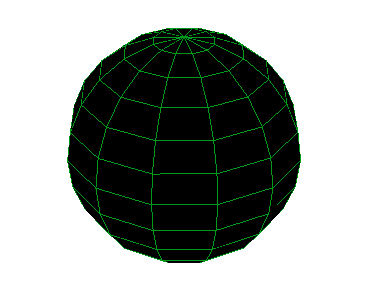
Removes the selected object completely from the scene. This is helpful for cleaning up unused or temporary assets.
UV Mapping Tools
 UV Checker
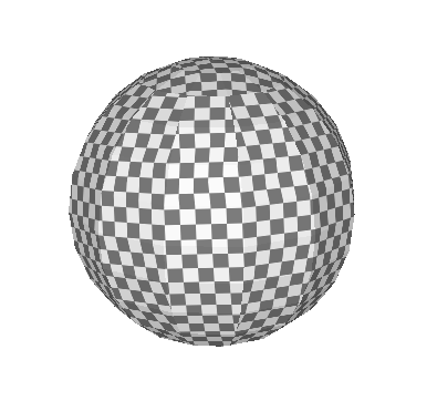
Toggles the display of a UV checker texture on the model. The checker pattern helps evaluating stretching, distortion, and texel density by providing a clear visual grid. When enabled, the surface becomes easier to analyze for UV layout consistency.
Switches between the checker pattern and the model’s original color texture, allowing fast comparison during the UV editing process.
UV Correction Slider
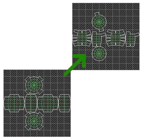
Adjusts the automatic UV unfolding by compensating for variations in surface orientation. This slider influences how strongly the geometry’s normals are taken into account when flattening the mesh, helping correct distortion on curved or angled surfaces.
Provides finer control over bounding-box-based unwrapping, especially for irregular shapes.
 Automatic UV Unfolding
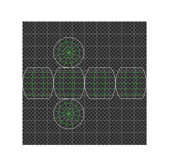
Generates UV coordinates based on the object’s bounding box orientation. The tool evaluates the geometry from six directions—left, right, top, bottom, front, and back—then applies an unfolding method that fits each face to the most appropriate plane.
Useful for quickly producing clean UVs for hard-surface models such as boxes, architectural parts, or mechanical components.
Cylindrical Rotation X/Y/Z
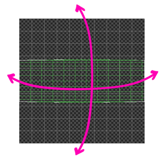
Allows precise numeric rotation of the cylindrical projection axis around the X, Y, or Z coordinate. These fields modify how the cylindrical unwrap aligns with the mesh, ensuring more predictable results on objects with directional curvature.
Ideal for tuning the projection for pipes, tubes, columns, and rounded shapes.
 Cylindrical Projection
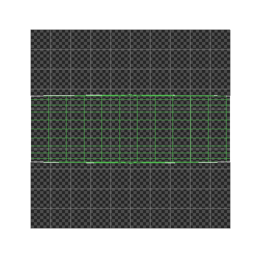
Applies a cylindrical UV projection to the selected faces. The method wraps the UVs around the object as if placing a label around a can, producing evenly distributed UV coordinates along curved surfaces.
Best suited for tubes, arms, ropes, columns, and any elongated form with radial symmetry.
 Normal Projection
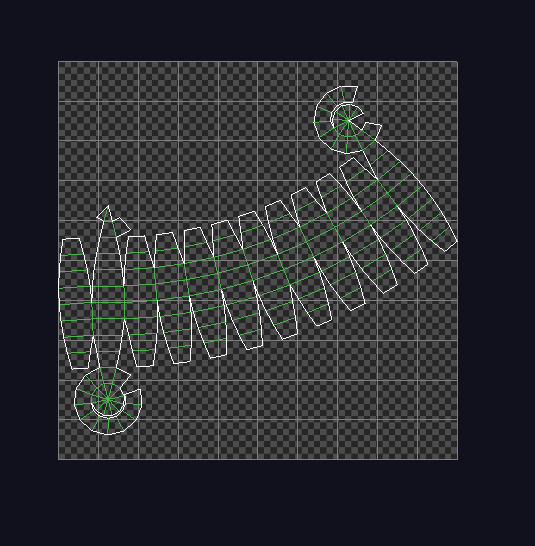
Automatically unfolds UVs by analyzing the geometry’s surface normals. This method groups faces according to their orientation and unfolds them to minimize visible seams when possible.
Provides a flexible, semi-automatic unwrap for organic shapes or objects with varied curvature.
 Split UV Edges
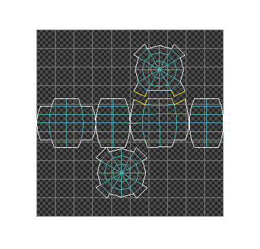
Separates the selected UV edges, creating independent UV islands. This is useful for manually controlling seams, allowing specific regions to unfold cleanly or to reduce texture distortion.
Often used when preparing a mesh for painting or baking, where clean borders are required.
 Weld UV Edges
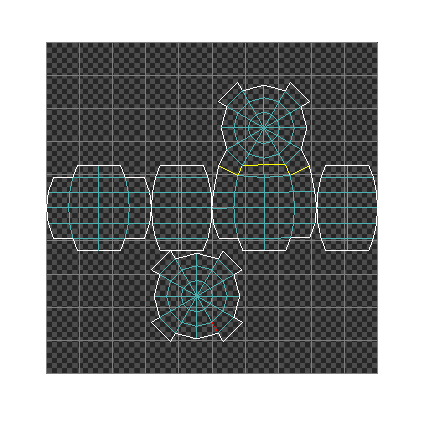
Joins two or more UV edges together into a single continuous seam. This operation reduces the number of UV islands and helps create smoother, unified regions in the texture layout.
Useful for restoring continuity after splitting or when combining previously separated shells.
 Split UVs
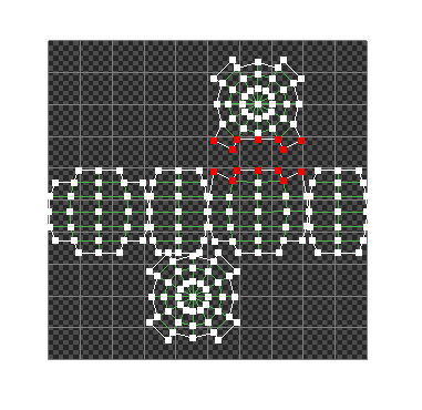
Detaches selected UV vertices, enabling finer manipulation of UV shells at the vertex level. This operation provides precision control when adjusting corners, tight bends, or overlapping UV elements.
Supports detailed UV refinement and shell isolation.
Weld UVs
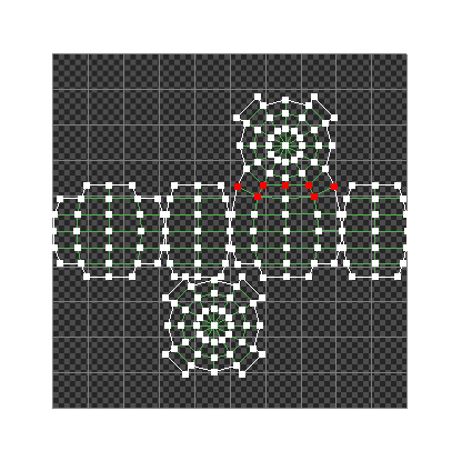
Joins two or more UVs together into a single continuous seam. This operation reduces the number of UV islands and helps create smoother, unified regions in the texture layout.
Useful for restoring continuity after splitting or when combining previously separated shells.
 Auto-Contain UV Map
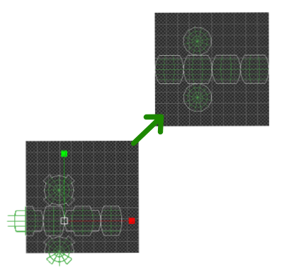
Automatically rescales and centers the UV layout to fit within the boundaries of the UV canvas. Ensures that all UV islands remain properly contained within the 0–1 texture space.
Helps standardize UV coordinates before exporting or baking textures.
 Repam Texture
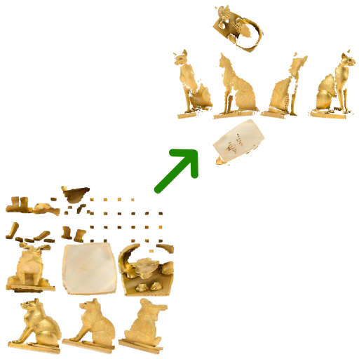
Transfers texture information from the selected UV region onto a new UV layout. This tool allows re-mapping existing texture data, preserving the look of a surface while modifying its underlying UV structure.
Helpful when updating UVs without losing baked or manually painted texture details.
 Export UV Map
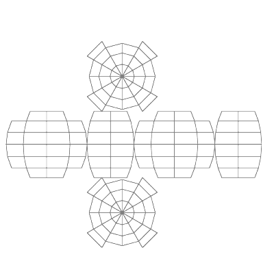
Exports the current UV layout as a PNG image. The exported image provides a clean wireframe representation of the UV shells, useful for painting textures in external applications.
Supports accurate hand-painted textures, stylized detail work, and visual debugging of UV organization.

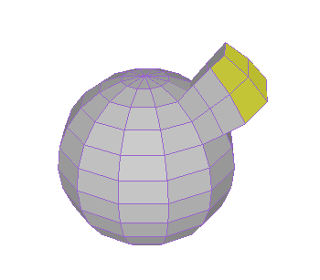
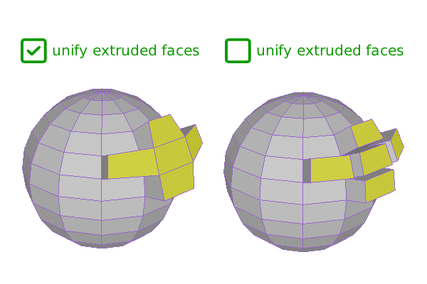
 Extrude
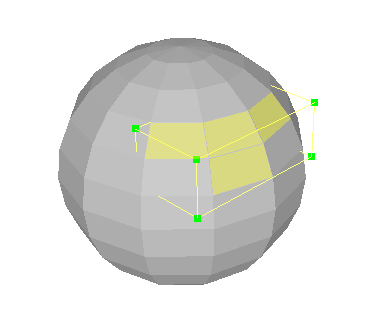
 Deform
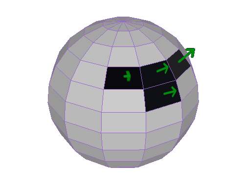
 Flip Normals
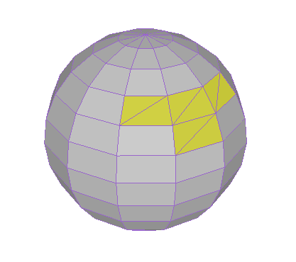
 Triangulate
 Fix Faces
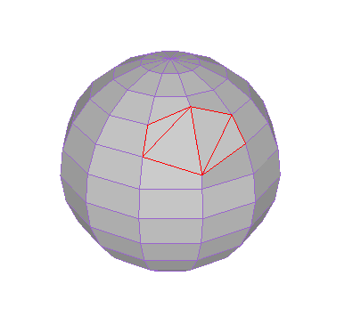
 Delete
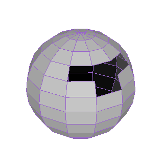
 Extrude
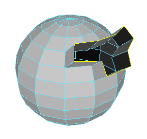
 Deform
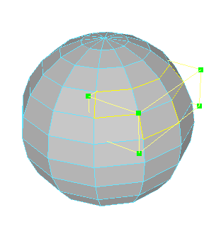
 Insert Edge Loop
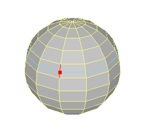
 Insert Edge
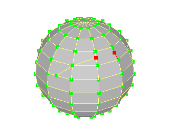
 Fill Hole
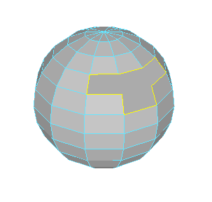
 Bridge
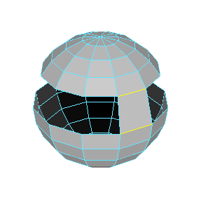
 Delete
 Merge
 Deform
 Delete